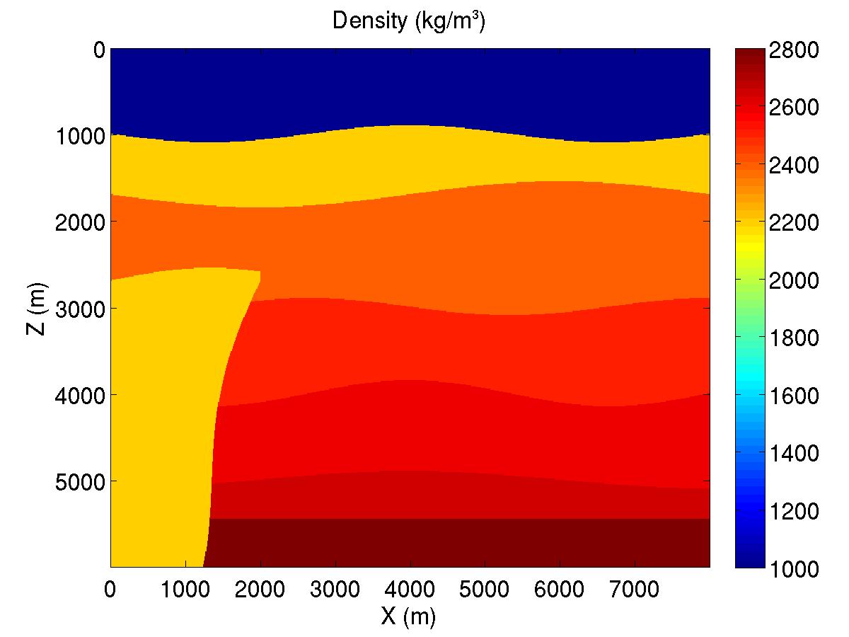
Theory: The salt flank can be imaged by forward propagating the incident wavefield and back propagating the wavefield reflected from the salt flank. In doing so, only a local velocity model around the well is required. This procedure approximates the VSP->SWP transform.
In implementation, the forward propagating can be simplified by a ray tracing. In this exercise, the time tables show the arrival times of the direct waves in the area left to the well. When the reflected wavefield is backward continued to the left, the energy happens at an image point and at the time of the direct wave arrival time can reveal the reflectivity at that image point. Lab exercise by Ruiqing He.
Objective: Execute program flankmig.m to image salt flank, and then stack all images.
Procedure: